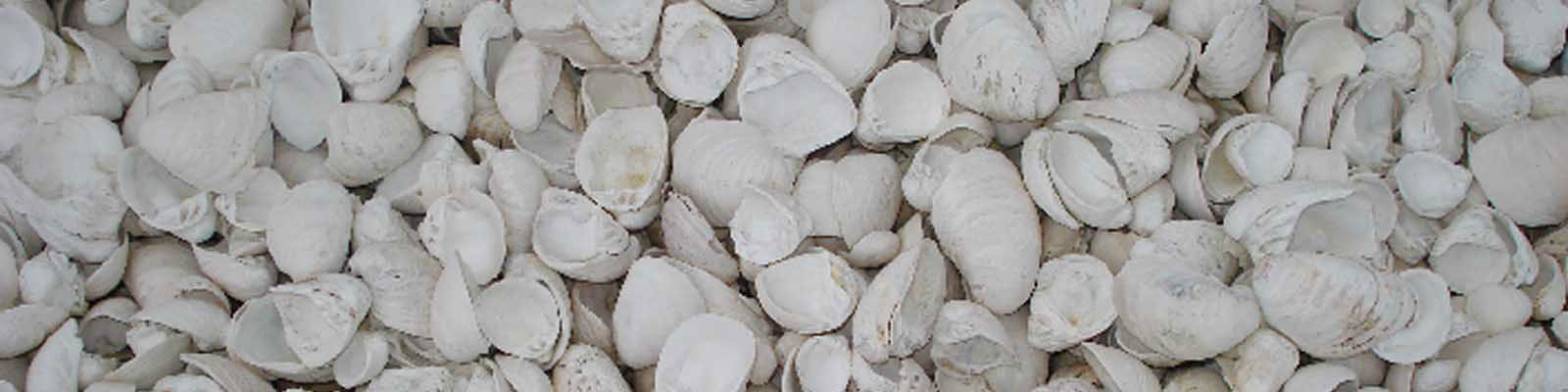
The raw materials used for the production of white cement are Lime shell, White clay, White sand and Gypsum. The production process consists of grinding the raw materials to a fine stage, blending them to a uniform composition and heating them to the point of incipient fusion when the cement compounds are formed. The white Portland cement is the product obtained by cooling and grinding the clinker thus formed with gypsum to a fine powder. The production process can be mainly divided into three stages :
The different processes under these main stages are :
The main raw material for the production of white cement – Lime shell, an underwater deposit in Vembanad Lake- is extracted using Cutter suction dredgers and brought to the company in barges. The company is having 2 dredgers named- Lokanathan of capacity 5000 gallons and Rudinger of capacity 3000 gallons. The total capacity of the two dredgers is about 30 tons per hour.

DREDGER WORKING AT VEMBANATTU KAYAL
The dredger is placed anywhere in the lake using a spud which is then at lowered position, while the other spud is at the raised position. The cutter is about 10 meters in length. It can cut the shell to a maximum depth of 30 Ft from the water level. For cutting, the cutter is placed downwards by using a winch. When spud-I is entered, whinch-1 is loosened and cutter moves to clockwise direction. Similarly when the spud-II is entered, the winch-II is loosed and cutter moves in anti-clockwise direction. A cutter motor rotates the cutter. The shell thus obtained is sucked and discharges by a centrifugal type dredge pump to the screening plant, effecting the primary washing. After primary washing, the shell is transferred to the wooden barges. Presently, company owns 2 nos cutter suction dredgers, 2 nos screening plant for primary washing of lime shell in the lake and 5 nos wooden barges each having a loading capacity 50MT of lime shell.
SHELL LOADING INTO THE BARGE
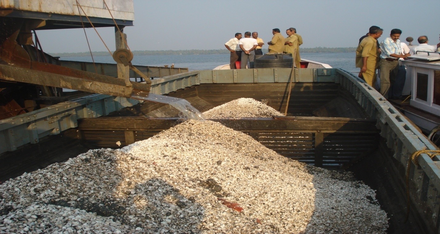
The shell extracted using Cutter suction dredger is brought to the plant in barges through lake. The shell received at the plant is unloaded at the unloading station where Secondary washing and cleaning at the plant is carried out.
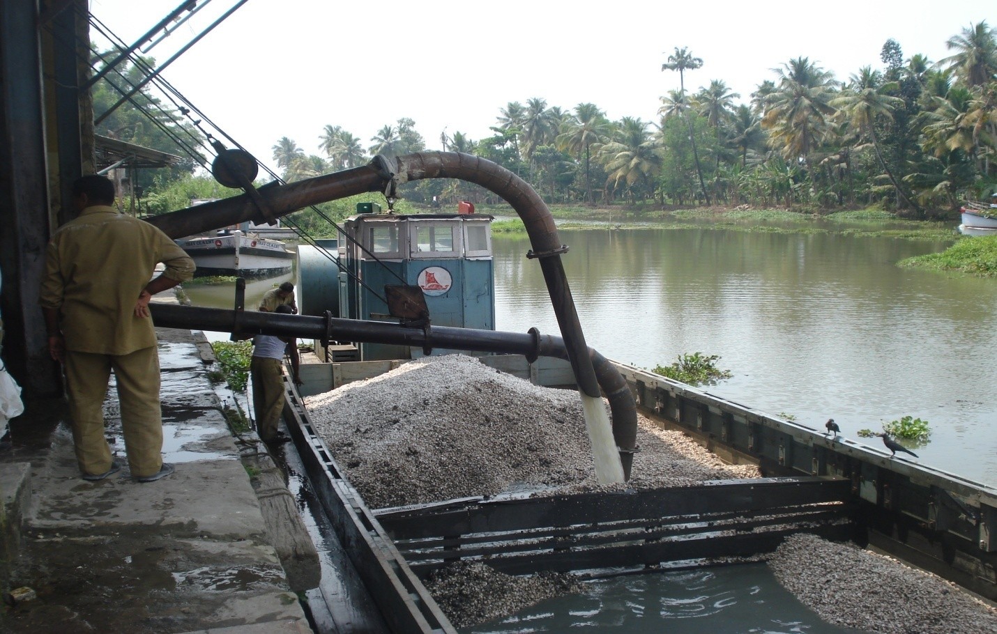
SHELL UNLOADING FROM BARGE
Shell in the barge is diluted with about 80-90% of water by means of diluting pump for easiness of suction. A suction pump (Gravel pump) draws water along with the shell to the receiving tank near the rotary grill of the screening plant. The shell is then passed through the rotary grill that rotates at a constant speed and the waste materials are washed out during its rotation. Cleaned shell is either passed to the belt conveyors through hoppers or stored outside depending on the requirement of the raw material for the process. There are 2 rubber belt conveyors (Conveyor I- short and horizontal, Conveyor II- long and inclined) for conveying the shell to the bal mill hopper or to the crane gantry.
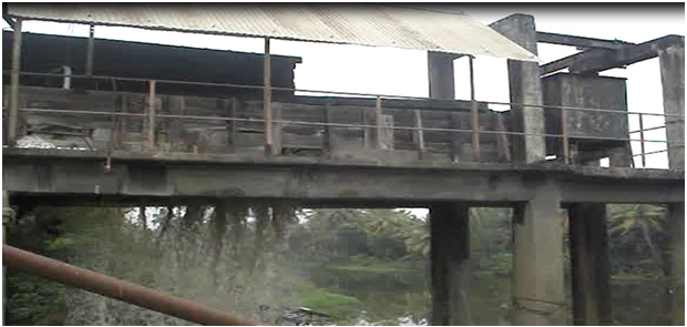
SHELL WASHING AT ROTARY GRILL 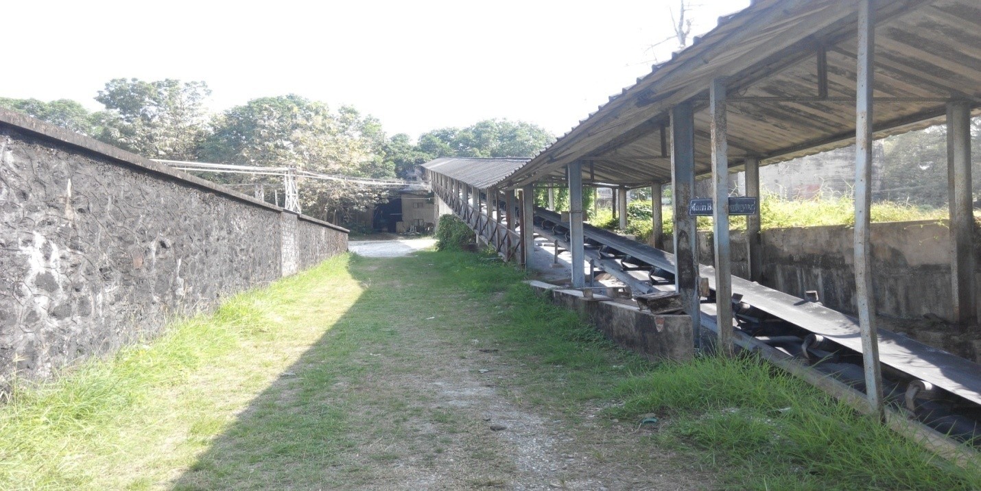
BELT CONVERYOR FOR TRANSPORTING LIME SHELL
Before taking the clay for process, the clay in the solid form is made into slurry form by mixing with water. This is done in a clay wash mill. Clay wash mill is a well like pit of RCC construction. Clay is put to the mill and about 65% water is also added during the grinding. Because of the hammering action of the weights provided in wash mill, clay is made to a slurry form known as clay slurry. The clay slurry is pumped to the storage tank(Clay silo), and it is taken from there for process when required.
For the slurry preparation, two grinding mills used are Roughing mill (Ball mill) and finishing mill (Raw mill).
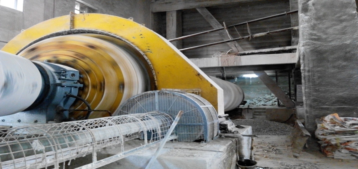
Ball mill is a cylindrical shell of large diameter to accommodate wear-resisting liners with sufficient space for feeding the material into and out of the mill.The shell along with the required amount of white sand and water is fed to the ball mill by a rotating feed table. The mill is partly filled with steel balls as grinding media. When the mill rotates, the materials are crushed to small particles. The material coming out of the ball mill is diverted to hammer screen by means of a slurry elevator. Fine particles sieves out the hammer screen are fed to the raw mill. The coarse materials return to the ball mill for further grinding.

BALL MILL
The raw mill is a hollow cylindrical shell, inside of which is lined with flint blocks to avoid contamination of iron in the slurry. The grinding media used is flint pebbles. The output from the ball mill and the clay from the silo are finely ground in the raw mill and the output of raw mill is transferred to the slurry pit.
Slurry discharged from the raw mill is stored in silos by means of pumps. The chemical composition of the slurry is adjusted at this stage. There are 3 silos for storing the slurry. The slurry from the silos is first collected in the correction pit and is transferred to the slurry basin. The slurry is given air agitation always. The slurry basin is an ordinary well type pit provided with mechanical and air agitation facility. From this, the slurry is taken to the rotary kiln through a scoop feeding mechanism.

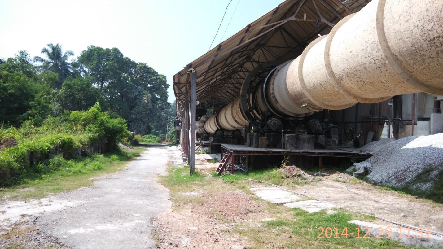
Kiln is a cylindrical steel shell lined with refractory bricks, mounted at an angle of 3o to the base on roller supports, so that it can be rotated. The kiln is having a length of about 285 feet and diameter of about 9 feet and is rotated at about 1 rpm by a DC motor. Slurry is fed to the kiln at the upper end by a scoop feeder. Since the feeder is synchronized with the kiln, it deliver slurry proportional to the speed of the kiln.
In the kiln, there are 3 zones called Drying zone, Calcining zone and Burning zone. The fuel used in the kiln is Furnace oil. The fuel is burned in the kiln using a pressure jet burner. The oil is pre-heated at a tempeterature of 100oC to 130oC by an electric heater for better atomization. Blower supplies primary air along with fuel. The secondary air is sucked through the coolers provided around the kiln by an ID fan, which drives the flue gas through the chimney. The air inlet to the kiln is controlled by the damper provided at the chimney side. The O2% in the flue gas is maintained around 2% to get the maximum fuel efficiency. To improve the heat transfer in the drying zone a system of chains are hung inside the shell, which absorbs the heat from the flue gas and transfer to the material to be dried. In the drying zone 99% of the water content in the slurry will be removed. In the calcining zone removal of CO2 takes place. This is represented by the formula given below.
CaCO3 -> CaO +CO2
After passing through the calcining zone, the materials enter the burning zone. The clinker is formed in the burning zone by fusing the compounds at about 1400oC. At this temperature,t the coloured ferric oxide of Iron is bleached to light green colour Ferrous oxide and thus the clinker is of light green colour is formed. The burned clinker is then quenched by sprayhing water. The steam produced from this water create a reducing atmosphere in the kiln which speeds the conversion of FeO2 to FeO and also it prevents the reverse reaction. The clinker then flows to nine coolers connected on Kiln’s periphery. The secondary air entering through the coolers exchange the heat and thus the clinker gets cooled and at the same time the air gets pre-heated, the clinker coming out the cooler will be usually granular form and there will be a small percentage of mass clinker. The bigger pieces are then crushed in the hammer crusher. The clinker is then conveyed to the clinker silo by means of shaker conveyor and bucket elevator. There are 2 silos of capacity about 2000 tonnes each.
Cement grinding mill is similar to that of Raw mill used for raw material finish grinding. There are 3 cement mills A, B and C mill with a clinker grinding capacity of 60 tph for A mill and 50 tph each for B mill and C mill. The B and C mills are identical in construction. A mill has got 2 chambers and for B & C mills 3 chambers each. Flint pebbles of different sizes are used as grinding media. The mills are lined with Felcite blocks. Clinker and Gypsum in the correct proportion is fed to the mill by a rotating feed table. The ground material (Cement coming out of the mill is conveyed to a clarifier (Separator) by means of a bucket elevator. In the separator the coarse particles which are separated flow to the mill and the finer particles flow to the flexo pump which is operated by compressed air. Using the flexo pump the cement is transferred to the cement silos located at the packing house.
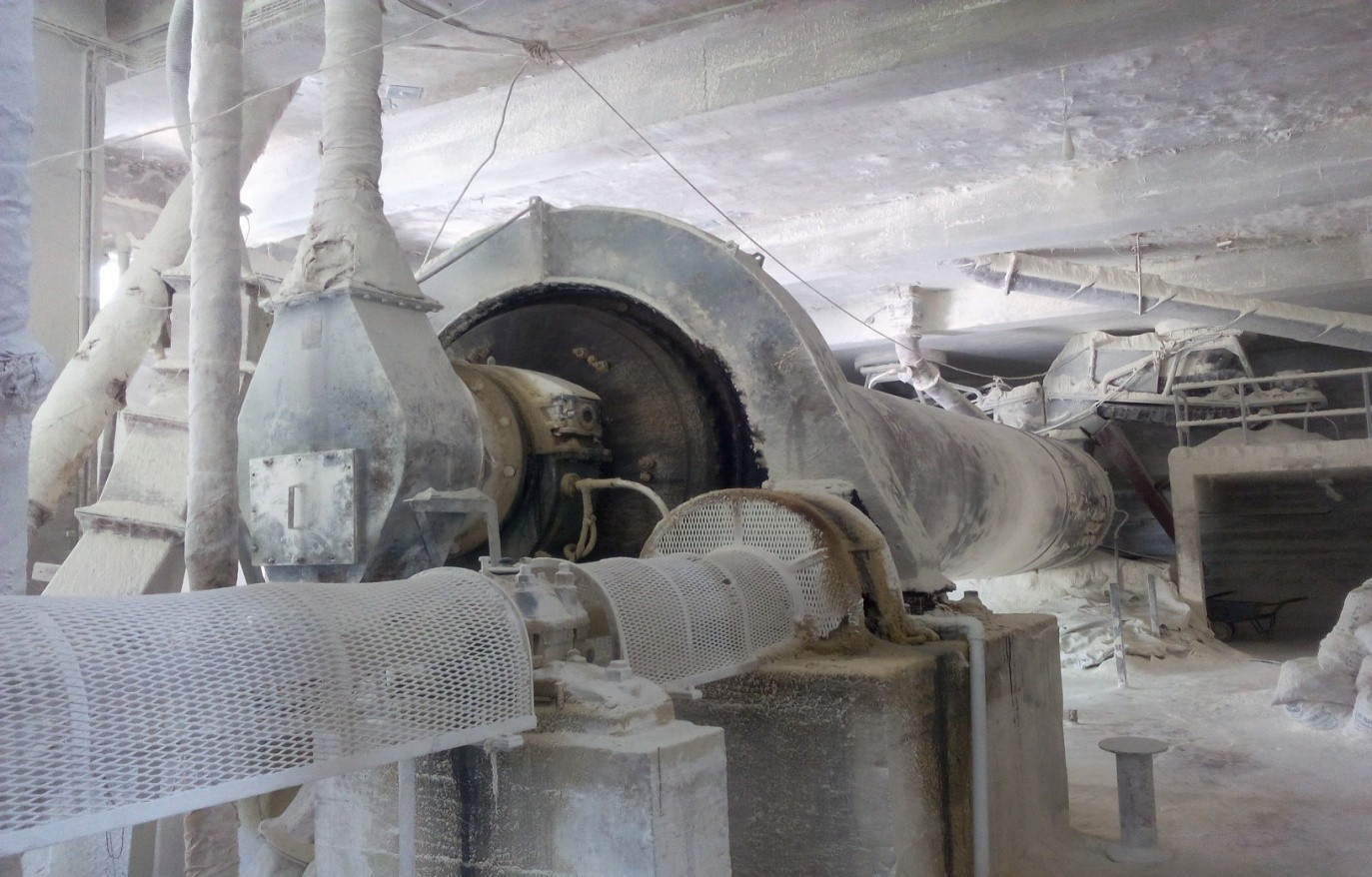
CEMENT MILL
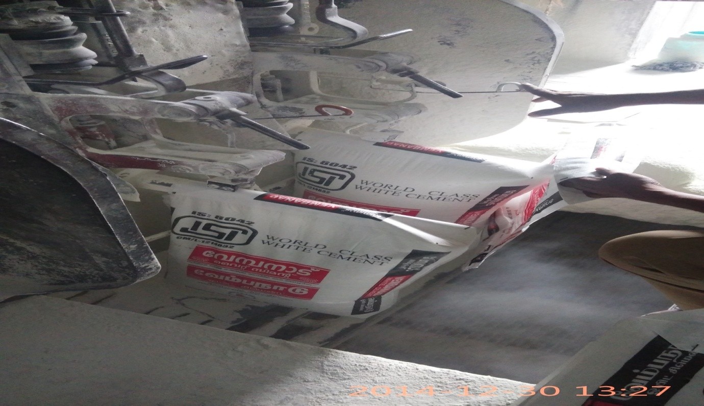
The White cement stored in silos is packed in bags in the packing house. Compressed air is used for the free flow of cement from the silo and the hopper located above the packing machine. Cement is conveyed from the silo to the packing machine hopper through screw conveyors and bucket elevator. The pressure created by the compressed air forces the cement to escape through the opening of the spout where the bag is fitted for packing. When the bag is filled with 50 Kgs., material discharges from the spout automatically. The spillage during packing will return to the elevator through a screw conveyor. The filled bags fall down from the spout to the wire net conveyor will be transferred to the truck through a fixed-point belt conveyor and a movable belt conveyor. A dust blower and a cyclone separator are provided at the packing house for the removal of dust. The white cement is packed in paper gunny bag.
Gazette Notification dated 22.12.2007 and 03.06.2008 by which the procedure for remittance of fee for providing information in the case of Public Authorities other than Government Departments is amended vide Government Order No. GO (P) No. 540/2007/GAD dated 18th December, 2007 as detailed below:
“provided that in the case of public authorities other than the Government Departments, the fee shall be remitted to the account of such public authority as provided in clauses (c) and (d) of rule 3”.
Clauses c & d are..